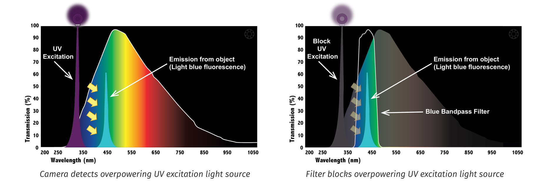
During fluorescence imaging, the item being inspected absorbs a shorter wavelength of light (usually ultraviolet (UV) light) that excites a specific fluorophore, causing it to release photons that fluoresce and emit light at a longer wavelength. In industrial applications this fluorescence is most often a blue color. By using an appropriate bandpass filter centered at the wavelength of the emission (such as a blue bandpass filter), all other wavelengths of light are blocked. Most importantly, excitation wavelength(s), which will always be far brighter than the fluorescent glow are blocked. In these types of applications, it’s mandatory to use a bandpass filter in order to effectively image the lower energy luminescence. UV fluorescence applications require a filter that blocks the UV light source, transmitting only the weaker fluorescence emission. Common fluorescent excitations include 365nm, 395nm and 400nm. It’s important to note that in UV fluorescence applications, the filter is used for passing the fluorescence emission wavelength and blocking the excitation light source.
Before: UV excited 2D matrix with a cyan fluorescence that is nearly overwhelmed by a UV light source and ambient light.
MidOptAfter: A BP505 Cyan Bandpass Filter used on the lens blocks the UV light source and other ambient light, passing the cyan fluorescence and thus creating necessary contrast.
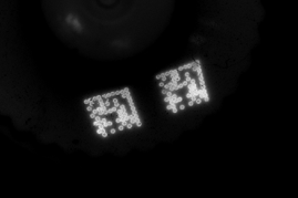
Before: Without a filter over the lens, the 395nm LED light overpowers the fluorescence emission that would allow the 2D matrix to be read by the camera.
MidOptAfter: A BP470 Blue Bandpass Filter mounted on the camera lens effectively blocks UV wavelengths, passing only the blue fluorescence emission from the 2D matrix while blocking all other unwanted light.
Before: A postal bar code printed on the back of an envelope for high speed sorting is excited under UV light. Without a filter on the camera, the orange characters go undetected. In this case, the camera sensor is overcome by visible and UV output from the light.
MidOptAfter: A BP590 Orange Bandpass Filter mounted on the lens creates greater contrast by passing the orange fluorescence while blocking UV, near-IR and other visible wavelengths.
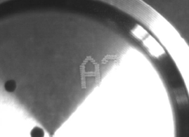
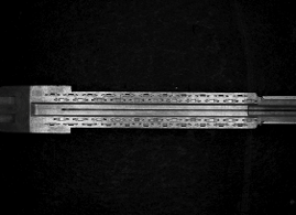
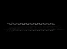
Before: Light from a UV LED light source overpowers blue fluorescence emitted by this part, making the characters virtually undetectable.
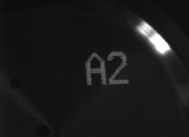
MidOptAfter: A BP470 Blue Bandpass Filter threaded to the lens blocks the overpowering UV light source, passing only the blue emission in the area of interest.
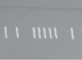
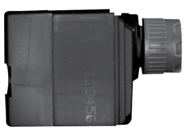
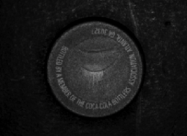
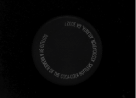
Before: The contrast between the UV-excited blue fluorescence and background is not sufficient to reliably image the code marking.
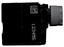
MidOptAfter: A BP470 Blue Bandpass Filter darkens the background by blocking reflected UV light used to excite the blue fluorescence, creating sufficient contrast.
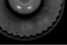
Before: The surfaces of a stent reflect light unevenly, making it difficult to selectively examine desired features.
MidOptAfter: The use of a PR032 Linear Polarizer and a BP635 Light Red Bandpass Filter, mounted together over the camera lens, eliminates glare and darkens the background to highlight the features of interest.
Before: Hundreds of tiny plastic particles in the bottle cap reflect light at certain angles, creating noise in the background. This interferes with the ability to inspect the characters printed on the cap.
MidOptAfter: A Linear Polarizer Filter mounted on the lens and properly aligned extinguishes the direct reflection of light from the particles, eliminating background noise entirely.
To find a distributor or to learn more about MidOpt Machine Vision Filters, Contact Us
We value your privacy.
We use cookies on our website to give you the most relevant experience by remembering your preferences and repeat visits. By clicking “Accept”, you consent to the use of ALL the cookies. However you may visit Cookie Settings to provide a controlled consent.
This website uses cookies to improve your experience while you navigate through the website. Out of these cookies, the cookies that are categorized as necessary are stored on your browser as they are essential for the working of basic functionalities of the website. We also use third-party cookies that help us analyze and understand how you use this website. These cookies will be stored in your browser only with your consent. You also have the option to opt-out of these cookies. But opting out of some of these cookies may have an effect on your browsing experience.
Necessary cookies are absolutely essential for the website to function properly. These cookies ensure basic functionalities and security features of the website, anonymously.
Cookie
Duration
Description
cookielawinfo-checkbox-analytics
11 months
This cookie is set by GDPR Cookie Consent plugin. The cookie is used to store the user consent for the cookies in the category "Analytics".
cookielawinfo-checkbox-functional
11 months
The cookie is set by GDPR cookie consent to record the user consent for the cookies in the category "Functional".
cookielawinfo-checkbox-necessary
11 months
This cookie is set by GDPR Cookie Consent plugin. The cookies is used to store the user consent for the cookies in the category "Necessary".
cookielawinfo-checkbox-others
11 months
This cookie is set by GDPR Cookie Consent plugin. The cookie is used to store the user consent for the cookies in the category "Other.
cookielawinfo-checkbox-performance
11 months
This cookie is set by GDPR Cookie Consent plugin. The cookie is used to store the user consent for the cookies in the category "Performance".
viewed_cookie_policy
11 months
The cookie is set by the GDPR Cookie Consent plugin and is used to store whether or not user has consented to the use of cookies. It does not store any personal data.
Functional cookies help to perform certain functionalities like sharing the content of the website on social media platforms, collect feedbacks, and other third-party features.
Performance cookies are used to understand and analyze the key performance indexes of the website which helps in delivering a better user experience for the visitors.
Analytical cookies are used to understand how visitors interact with the website. These cookies help provide information on metrics the number of visitors, bounce rate, traffic source, etc.
Advertisement cookies are used to provide visitors with relevant ads and marketing campaigns. These cookies track visitors across websites and collect information to provide customized ads.